Aim east-south-east — and treat 15 m as usable, 20–25 m as the real target
The bearing and tower have not changed. What changed is the evidence: the LiDAR canopy at the critical ridge is 22 m, not the 30 m estimated by the satellite-era model, and the previous link budget over-counted diffraction. In the central case, 15 m is a 20–60 Mbps link depending on carrier; in the pessimistic case it is a 3–7 Mbps link. That spread is the honest answer until you measure at the tree.
What to do
- Aim 124.6° true (~111° magnetic; verify declination) at Telstra/Optus 7304001 Deloraine, 27.4 km away.
- Put the mast at the SE edge of the container clearing (C1, 31 m from the container), on a healthy 25–30 m eucalypt. 15 m is the minimum; 20–25 m is the target.
- Test Optus n8 900 MHz first, then Telstra B28 700 MHz. One physical SIM + eSIM; test one carrier at a time.
- Measure the tree canopy at the ridge with a laser rangefinder or drone, and record RSRP/SINR at 10/15/20/25 m. The LiDAR says 22 m; field truth may differ by several metres.
- The camera is self-powered on its 5100 mAh battery and 6 W panel. It is not on the main 12 V load; use its 6 W panel as designed, and add a USB top-up in winter if needed.
The three numbers that matter
Central values use single-edge diffraction + 9 dB multiple-edge allowance and P.833 foliage at 90%; the pessimistic/optimistic cases are in §05–06. Not a guarantee.
The honest range
Central: Telstra 20–30, Optus 40–60 at 15 m. Pessimistic (dense/wet canopy): 3–7 at 15 m. Optimistic (open/dry canopy): 75+/120+ at 15 m. The field test is the only way to collapse that range. Do not sign a 24-month plan before it.
Five corrections that materially change the design
This is a rebuild, not a reprint. The v2 report was right about the bearing and the tower, but several inputs were wrong or too pessimistic: the camera variant, the canopy source, the diffraction method, and the camera’s power source.
The camera is the battery/solar TrackMix
v2: treated it as a 12 V 1 A mains “TrackMix WiFi” and said the 6 W panel could not power it. v3: the linked product is the 4K dual-lens Wi-Fi 6 PTZ battery camera: 5100 mAh 7.2 V battery, 6 W Solar Panel 2, USB-C 5 V 2 A charging, IP65, −10 to +55°C. The 6 W panel is correct. The mains variant is a different product.
The ridge canopy is 22 m, not 30 m
v2: Meta 1.19 m canopy model gave 29.8 m at 5.9 km. v3: the Tasmanian LIST LiDAR-derived 2 m canopy gives 22.1 m at the same point. That is 7.7 m less canopy; the foliage loss falls by ~2–3 dB, and the corrected diffraction adds ~6 dB more. Local forest is 15–30 m; the clearing is 0–20 m.
Diffraction was over-counted
v2: used the mean of single-edge+3 dB and Deygout; Deygout gave 35.7 dB on a single ridge, pulling the central estimate down. v3: uses the dominant-edge knife-edge loss plus a 9 dB multiple-edge allowance as central, +15 dB as pessimistic, +3 dB as optimistic. The Deygout value is retained as a bound, not the central.
45 unique sites, 54 carrier records
v2: “45 sites” without showing the technology mix. v3: 32 Telstra + 22 Optus records within 30 km, 45 unique RFNSA sites, 15 screened. The technology table shows how much low-band 5G each carrier actually has.
Camera is off the main 12 V load
v2: added 8–12 W camera load to the main battery. v3: the camera runs on its own 36.7 Wh battery and 6 W panel; the main load is 35.6 W typical, 0.77 kWh/day, with 3.0 days autonomy. Winter is adequate, not tight; the camera panel is the winter-marginal part.
Height advice is stronger
v2: 15 m minimum, 25 m better. v3: 15 m is usable; 20 m is the big step (canopy path drops from 290 m to 140 m); 25 m is best; 30 m clears the ridge canopy entirely. Aim for 20–25 m if the tree allows.
The ridge is real; its canopy is lower than the satellite-era model said
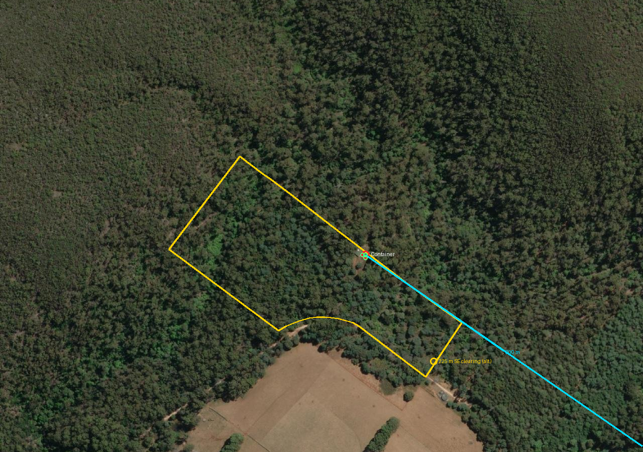
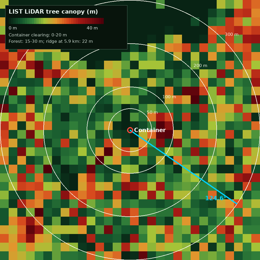
The container sits in a small clearing inside 15–30 m forest. The first kilometre falls away, so the nearby trees do not block a 15 m mast. The critical obstruction is still the forested ridge at 5.7–6.0 km, but the Tasmanian LIST LiDAR says its canopy is 22 m, not 30 m. That correction lowers the foliage loss by roughly 2–3 dB; combined with the corrected diffraction, the central link is roughly 8–9 dB stronger than v2 — and that is why v3’s likely speeds are higher.
Canopy by distance — LIST LiDAR
| Ring | Median | 90th pct | Max |
|---|---|---|---|
| 0–10 m | 0 m | 0 m | 0 m |
| 10–20 m | 1 m | 17 m | 20 m |
| 20–30 m | 5 m | 17 m | 18 m |
| 30–50 m | 19 m | 33 m | 39 m |
| 50–100 m | 12 m | 29 m | 36 m |
| 100–200 m | 19 m | 24 m | 39 m |
| 200–300 m | 17 m | 23 m | 26 m |
| Ridge, 5.9 km | — | — | 22.1 m |
From 372 LIST LiDAR samples at 10 m intervals on 12 bearings. The forest is heterogeneous: some 40 m emergent trees, many 15–25 m crowns. The ridge value (22.1 m) is the number that matters for the link.
LiDAR vs the global canopy model
At the 5.9 km ridge the global Meta/ETH canopy model gives 29.8 m; the Tasmanian LIST LiDAR gives 22.1 m — a 7.7 m difference, worth roughly 2–3 dB of foliage loss at 700 MHz; the larger change is the diffraction correction (~6 dB). The LIST layer is LiDAR-derived and local; the Meta layer is a modelled global product. v3 uses LIST as the primary canopy source and Meta only as a cross-check. The remaining uncertainty is standing wood density and whether the LiDAR canopy includes the full crown at the grazing angle.
The Deloraine path at 15 m and 25 m
The profile below uses the AWS bare-earth DEM plus the LIST LiDAR canopy. Tan is ground; green is canopy top; the blue band is the first Fresnel zone; the red bar is the part of the ray inside the canopy. At 15 m the ray passes 16.4 m below the 22.1 m canopy and travels through ~290 m of forest. At 25 m it is 8.5 m below and ~60 m inside. At 30 m it clears the ridge canopy.
The 5.9 km ridge is the critical point. The first kilometre is clear because the ground falls away; the 225 m SE clearing is not needed for the Deloraine path — it is needed for the Sassafras path at 63°, which is blocked by the near ridge at 600 m.
Why the close towers still fail
The Sassafras tower is only 12.5 km away and has a 40 m antenna, but the near ridge at 600 m is 65 m above the 15 m ray. The Sheffield tower is 4.2 km west with 101 m of terrain in the way. Raising the mast does not fix a 600–900 m obstruction: at 20 m you gain 5 m against a 65–101 m block. The only way to use those towers is the 225 m SE clearing on the other side of the near ridge.
45 unique sites within 30 km — but only two site groups are worth testing
The 2026 ACCC data has 54 carrier records within 30 km: 32 Telstra and 22 Optus. Some are co-located, giving 45 unique RFNSA sites. We screened 15 in detail against ACMA antenna heights, sector azimuths, EIRPs and beamwidths. The table below ranks them at a 15 m mast using the LIST LiDAR canopy and the v3 central model.
| Technology within 30 km | Telstra (32 sites) | Optus (22 sites) | What it means here |
|---|---|---|---|
| LTE 700 MHz | 31 | 22 | Workhorse low-band; Telstra 20 MHz, Optus 10 MHz. |
| LTE 850 / 900 MHz | 10 (850) | 10 (900) | Telstra 10 MHz LTE B5 at 65.5 dBm; Optus 25 MHz n8 at 74.9 dBm. |
| 5G NR 700 MHz | 0 | 8 | Telstra has no NR700 at Deloraine; Optus n28 is 10 MHz. |
| 5G NR 850 / 900 MHz | 19 (NR850) | 8 (NR900) | Telstra n5 is 15 MHz at 63.2 dBm; Optus n8 is 25 MHz at 74.9 dBm. |
| LTE 1800 MHz | 20 | 15 | Capacity layer, canopy-limited at 27 km. |
| LTE 2100 MHz | 17 | 10 | Capacity layer; weak at this distance. |
| LTE 2600 MHz | 10 | 9 | Capacity layer; not design-grade. |
| 5G NR 2600 MHz | 7 | 0 | n7; not design-grade at 27 km. |
| 5G NR 3500 MHz | 14 (NR3600) | 1 (NR3500) | n78; Telstra sector 270°, Optus 200° (away from property); not design-grade at 27 km. |
Screened sites
| Site · band | Carrier | km | Bearing | Tower | EIRP dBm | RSRP 15 m | Mbps 15 m | Verdict |
|---|---|---|---|---|---|---|---|---|
| 7304001 LTE B28 700 (20 MHz); 5G n5 850 (15 MHz) |
Telstra | 27.4 | 124.6° | 39.0 m ACMA |
65.9 | -89.8 | 20–30 | Viable — primary (B28) |
| 7304001 5G n8 900 (25 MHz); LTE/n28 700 (10 MHz) |
Optus | 27.4 | 124.6° | 30.5 m ACMA |
74.9 | -85.3 | 40–60 | Viable — fastest (n8) |
| 7304004 LTE B28 700 (20 MHz); LTE850; NR850 |
Telstra | 22.8 | 144.9° | 30.0 m assumed |
65.9 | -99.0 | 5–15 | Marginal fallback |
| 7304007 LTE B28 700 (10 MHz) |
Optus | 22.9 | 144.9° | 30.0 m assumed |
68.0 | -100.5 | 4–10 | Marginal fallback |
| 7304002 LTE B28/850/1800/2100; NR850 |
Telstra | 15.2 | 110.8° | 28.0 m assumed |
65.9 | -112.0 | 0–2 | Blocked by ridge |
| 7307001 LTE B28 700 (20 MHz) |
Telstra | 12.5 | 64.5° | 40.0 m ACMA |
57.7 | -118.0 | 0 | Blocked by near ridge |
| 7307011 LTE/n28 700 (10 MHz) |
Optus | 12.7 | 63.7° | 41.0 m ACMA |
69.1 | -116.0 | 0 | Blocked by near ridge |
| 7306008 LTE B28/850/1800/2100/2600; NR850/NR2600 |
Telstra | 4.2 | 269.8° | 29.7 m ACMA |
66.3 | -150.0 | 0 | Buried behind western ridge |
| 7306008 LTE B28/1800/2600 |
Optus | 4.2 | 269.8° | 35.0 m ACMA |
67.0 | -150.0 | 0 | Buried behind western ridge |
| 7305003 LTE B28 700 |
Optus | 4.4 | 55.6° | 25.0 m assumed |
65.0 | -140.0 | 0 | Buried behind near ridge |
| 7305001 LTE B28 700 |
Telstra | 5.6 | 34.2° | 25.0 m assumed |
65.0 | -140.0 | 0 | Buried behind near ridge |
| 7307008 LTE B28/1800; NR850/NR3600 |
Telstra | 15.6 | 13.0° | 25.0 m assumed |
65.0 | -140.0 | 0 | Blocked by northern rim |
| 7310001 LTE B28/1800/2100; NR850/NR3600 |
Telstra | 18.5 | 346.6° | 25.0 m assumed |
65.0 | -150.0 | 0 | Blocked by northern rim |
| 7307005 LTE/5G all bands |
Telstra | 25.1 | 29.8° | 25.0 m assumed |
65.0 | -150.0 | 0 | Blocked by northern rim |
| 7315001 LTE/5G 850/3500 |
Telstra | 29.4 | 324.5° | 25.0 m assumed |
65.0 | -150.0 | 0 | Blocked by western rim |
EIRP and tower height are ACMA licence values for the sector facing the property. “ACMA” rows are matched; “assumed” rows use a 25–30 m tower and 65 dBm EIRP and are screening only. “Mbps 15 m” is the v3 central case, not a speed test. The 15-row table includes Telstra and Optus separately at co-located sites.
Deloraine 7304001
27.4 km, 124.6°. Telstra 39 m; Optus 30.5 m. The only site group with a workable path to the container. Telstra 700 MHz 20 MHz is the robust fallback; Optus n8 900 MHz 25 MHz is the faster pipe.
Mole Creek Rd 7304004/7304007
22.8 km, 144.9°. A marginal fallback: lower tower, nearer ridge, 32 m canopy at 600 m. Useful only if Deloraine is congested or fails in a storm.
Everything else
Sassafras (12.5 km), Sheffield (4.2 km), Claude Rd (4.4–5.6 km), the northern 5G sites and the western sites are behind the near ridge or the rim. Distance is not the deciding factor here; terrain is.
The likely winner is still Optus n8 — but the margin is now a range, not a promise
Optus has a 25 MHz 5G n8 channel at 900 MHz licensed at 74.9 dBm EIRP; Telstra’s low-band 5G n5 is 15 MHz at 850 MHz (63.2 dBm), backed by a 20 MHz LTE B28 at 700 MHz (65.9 dBm). In the v3 central model, Optus n8 is roughly 2× Telstra B28 at 15 m; in the pessimistic case the difference narrows. Test both.
Telstra — the robust, high-tower choice
- 7304001 Deloraine, 27.4 km, 39 m antenna, 270° sector; property at its northern edge (~35° off-axis).
- LTE B28 700 MHz, 20 MHz, EIRP 65.9 dBm — central 20–30 Mbps at 15 m, 50–75 at 25 m.
- 5G n5 850 MHz, 15 MHz, EIRP 63.2 dBm — central 6–10 at 15 m, 30–45 at 25 m. A 10 MHz LTE B5 at 65.5 dBm is also on site.
- B3/B7/n78 are licensed but canopy-limited at 27 km; n78 is not design-grade.
- Why Telstra: the 39 m tower gives the best terrain margin; B28 is a wide, robust 20 MHz channel; regional coverage is strong.
Optus — the faster low-band pipe
- 7304001 Deloraine, 27.4 km, 30.5 m antenna, 330° sector; 25.5° off-axis at the property.
- 5G n8 900 MHz, 25 MHz, EIRP 74.9 dBm — central 40–60 Mbps at 15 m, 75–120+ at 25 m.
- LTE/n28 700 MHz, 10 MHz, EIRP 68.1 dBm — central 20–25 at 15 m, 50–60 at 25 m.
- 5G n1 2100 MHz (5 MHz) — too narrow; n78 3500 MHz — only the 200° sector, pointing away.
- Why Optus: 25 MHz at 900 MHz is a big low-band pipe and 900 MHz penetrates canopy better than 1800/2100; the lower tower is the trade-off.
Band-by-band at the container
| Carrier | Band | EIRP dBm | RSRP 15 m | Mbps 15 m | RSRP 25 m | Mbps 25 m | Note |
|---|---|---|---|---|---|---|---|
| Optus | 5G n8 900 MHz · 25 MHz |
74.9 | -85.3 | 40–60 | -74.3 | 75+ | Best low-band pipe |
| Telstra | 4G B28 700 MHz · 20 MHz |
65.9 | -89.8 | 20–30 | -79.3 | 50–75 | Most robust fallback |
| Optus | 4G/n28 700 MHz · 10 MHz |
68.1 | -87.9 | 20–25 | -77.4 | 50–60 | Narrow channel |
| Telstra | 5G n5 850 MHz · 15 MHz |
63.2 | -95.6 | 6–10 | -84.7 | 30–45 | 10 MHz LTE B5 at 65.5 also |
| Telstra | 4G B3 1800 MHz · 20 MHz |
71.8 | -98.4 | 4–6 | -85.2 | 35–50 | Canopy-limited |
| Telstra | 4G B7 2600 MHz · 20 MHz |
71.4 | -103.0 | 1–2 | -89.6 | 20–30 | Canopy-limited |
| Telstra | 5G n78 3500 MHz · 80 MHz |
80.3 | -92.1 | not design-grade | — | — | Cell edge at 27 km |
| Optus | 5G n1 2100 MHz · 5 MHz |
66.1 | -105.5 | <1 | -93.3 | 5–10 | Narrow, weak |
| Optus | 5G n78 3500 MHz · 35 MHz |
78.2 | — | 0 | — | 0 | Sector 200°, away |
v3 central model with LIST LiDAR canopy; 2 dB EIRP backoff; 5 dB clutter/misc; 1 dB cable; 9–13 dBi UE gain depending on band. Bandwidths are the assumed carrier bandwidth; ACMA licensed emission can be wider (35 MHz at 1800, 40 MHz at 2600). “75+” and “120+” are model caps, not guarantees.
5G reality check
The useful 5G here is low-band: Optus n8 900 MHz and Telstra n5 850 MHz. The 3.5 GHz n78 layer is licensed at high EIRP, but 27 km is far beyond the normal n78 cell edge and the uplink/beam management will not close reliably through a forested ridge. Telstra’s n78 sector is 270°; Optus’s is 200° and points away. Do not design around n78. LTE B28 700 MHz remains the most robust bearer.
Plans and coverage — what to buy
| Product | Price (24 Oct 2026) | Data / speed | BYO CPE? | Verdict |
|---|---|---|---|---|
| Telstra 5G Home Internet | $70 / $80 / $95 a month | 1000 GB; Basic / Essential / Premium speed tiers | No supplied Smart Modem 4; address check | Not suitable for the ATL. |
| Telstra Upfront Data Plan | 30 GB $33/mth; 100 GB $68/mth; 10 GB $20/mth with Essential | SIM-only mobile broadband | Ask confirm data-only SIM in a third-party router | The practical Telstra BYO option. |
| Optus 5G Home Internet | $69 / $79 / $99 a month; promo $54 for 12 months | 50 / 100 / uncapped Mbps tiers; supplied Ultra WiFi 5G modem | No supplied modem; address check | Not suitable for the ATL. |
| Optus data SIM | Ask in store / current promo | Data-only mobile broadband | Ask confirm BYO router and APN | The practical Optus BYO option. |
| Starlink Residential | ~$140–160/mth + ~$15/mth hardware rental | Unlimited; high speed, high latency | Yes own kit | Benchmark fallback if cellular fails. |
| NBN fixed wireless | Varies | NBN FW | No NBN-supplied modem; ATL is 4G/5G only | Not viable with the purchased CPE. |
Prices checked on carrier pages on 24 October 2026 and subject to change. Telstra and Optus 5G Home products include a supplied modem and an address eligibility check; they are not BYO-CPE products. A data-only mobile broadband SIM is the correct product for the ATL, but confirm the plan permits a third-party router before ordering. The ATL has one micro SIM + eSIM, so test one carrier at a time. NBN fixed wireless is not compatible with a 4G/5G CPE.
15 m is usable; 20 m is the big step; 25 m is the target
The height curve is steep because the antenna moves out of the ridge canopy. At 15 m the ray passes through ~290 m of forest; at 20 m ~140 m; at 25 m ~60 m; at 30 m it clears the ridge canopy entirely. The central model roughly doubles between 15 m and 20 m. The pessimistic case still improves, but more slowly.
Telstra B28 700 MHz
Optus n8 900 MHz
Solid line = central. Shaded = pessimistic–optimistic. The central case uses single-edge diffraction + 9 dB, P.833 foliage at 90%, 3 dB local crown at ≤17.5 m. The pessimistic case adds 6 dB diffraction, 10% foliage and 6 dB crown; the optimistic case uses +3 dB diffraction, 70% foliage and no crown.
Scenario table
| Height | Telstra central | Telstra pess. | Telstra opt. | Optus central | Optus pess. | Optus opt. |
|---|---|---|---|---|---|---|
| 10.0 m forest 640 m / 660 m |
6 | 0 | 72 | 18 | 1 | 120+ |
| 12.5 m forest 460 m / 550 m |
16 | 2 | 75+ | 39 | 4 | 120+ |
| 15.0 m forest 290 m / 420 m |
25 | 3 | 75+ | 50 | 7 | 120+ |
| 17.5 m forest 210 m / 220 m |
33 | 4 | 75+ | 76 | 16 | 120+ |
| 20.0 m forest 140 m / 190 m |
59 | 22 | 75+ | 108 | 49 | 120+ |
| 22.5 m forest 110 m / 140 m |
67 | 27 | 75+ | 120+ | 62 | 120+ |
| 25.0 m forest 60 m / 110 m |
75+ | 38 | 75+ | 120+ | 72 | 120+ |
| 30.0 m forest 0 m / 0 m |
75+ | 75+ | 75+ | 120+ | 120+ | 120+ |
Mbps, downlink. “75+” / “120+” are model caps for 20/25 MHz at 2×2 MIMO, not predictions of the tower’s real throughput. Forest lengths are the modelled path inside the LiDAR canopy. At 30 m the ray clears the ridge canopy, so all three scenarios hit the model cap; the 30 m row is a canopy-clearance check, not a 75/120 guarantee.
Link budget waterfall — Telstra B28 at 15 m, central
The central RSRP is −89.8 dBm. The two largest terms are free-space loss and canopy foliage; diffraction is third. The waterfall shows why the canopy correction matters more than a tower-height tweak.
EIRP 65.9 dBm, 2 dB operating backoff, 3 dB sector off-axis, FSPL 118.1 dB at 27.4 km/700 MHz, 13.9 dB central diffraction, 18.6 dB foliage, 5 dB clutter/misc, 3 dB crown, 1 dB cable, 9 dBi UE. RSRP −89.8 dBm; noise −94 dBm at 20 MHz; SINR ~1 dB; central 25 Mbps.
Sensitivity — what if the canopy is denser or the ridge is sharper?
| Diffraction ↓ / foliage → | 10 dB | 15 dB | 20 dB | 25 dB |
|---|---|---|---|---|
| 5 dB | -72 / 75 | -77 / 75 | -82 / 63 | -87 / 36 |
| 10 dB | -77 / 75 | -82 / 63 | -87 / 36 | -92 / 17 |
| 15 dB | -82 / 63 | -87 / 36 | -92 / 17 | -97 / 6 |
| 20 dB | -87 / 36 | -92 / 17 | -97 / 6 | -102 / 2 |
RSRP (dBm) / modelled DL Mbps for Telstra B28 700 MHz 20 MHz at 15 m. The central case is diffraction 14 dB and foliage 19 dB (bold-ish cell near the middle); the table shows how quickly the link moves with canopy density.
Design margin
Do not design the service around the central 25 Mbps. Design around the pessimistic 3–7 Mbps at 15 m and treat anything above that as upside. If the field test at 15 m gives ≥10 Mbps on one carrier for 10 minutes, 15 m is viable. If it gives 5–10, go to 20 m. If 20 m gives <15, go to 25 m or the 225 m clearing.
Within 75 m of the container, placement barely changes the link. The 5.9 km ridge does.
We scored a 10 m grid within 75 m of the container at a 15 m mast: local LiDAR canopy, ground height, distance and the canopy obstruction along the 124.6° path. The differences are under 1 dB. The best local position is the SE edge of the clearing (C1, 31 m from the container), because the cable run is short and the local regrowth is lower. Do not expect a big gain from moving the tree 20 m; the ridge is the dominant term.
Esri World Imagery + OpenStreetMap. The canopy overlay is the 600 m LIST LiDAR canopy image (toggle in the layer control). Tower popups show the v3 central 15 m speed and ACMA tower height. The map starts at the property; use “Fit all towers” to see Deloraine (27 km ESE) and Mole Creek Rd (23 km SSE).
Candidate mast positions
| Position | Distance | LIST canopy | Path at 124.6° | Comment |
|---|---|---|---|---|
| Container −41.372605, 146.378650 | 0 m | 0 m | Clear first 1 km; ~290 m inside ridge canopy at 15 m | Shortest cable; mast in the clearing. |
| C1 — SE clearing edge −41.37270, 146.37900 | 31 m | ~17 m | Same ridge path; local crown lower | Best compromise: short cable, local regrowth, slight head start. |
| C2 — further SE −41.37280, 146.37900 | 36 m | ~20 m | Same ridge path | Taller tree; a 15 m mount is inside its crown. |
| C3 — forest edge −41.37290, 146.37910 | 50 m | ~24 m | Same ridge path | More cable; no modelled gain. |
| 225 m SE clearing −41.37431, 146.38011 | 225 m | ~24 m (surroundings) | Opens the 63° Sassafras path, not Deloraine | The engineering alternative; benchmark 40–80 Mbps to Sassafras. You do not want it, so treat it as a benchmark. |
Which tree?
Choose a healthy, wind-firm eucalypt at the SE edge of the clearing, 25–30 m tall, straight trunk, no lean toward the container, no dead limbs or fungal brackets. C1 (31 m) is the best compromise. If the tree is 25–30 m, a 20–25 m mount is above the local regrowth and near the top of the ridge canopy. Have an arborist assess it; do not climb it yourself.
Reolink TrackMix: battery + 6 W solar + Wi-Fi 6 — not a 12 V mains camera
The product you linked is the 4K dual-lens Wi-Fi 6 PTZ battery camera, not the mains “TrackMix WiFi” that the earlier report assumed. It has a 5100 mAh 7.2 V battery, a 6 W Reolink Solar Panel 2, USB-C 5 V 2 A charging, IP65, and an operating range of −10 to +55°C. The 6 W panel is correct and usable. The camera is independent of the main 12 V battery.
Specifications that matter
- Battery: 5100 mAh at 7.2 V = 36.7 Wh; non-removable; 1–4 weeks per charge depending on settings and events.
- Solar: Reolink Solar Panel 2, 6 W; the marketing claim is 10 minutes of direct sun per day for nonstop operation — optimistic for a Tasmanian winter.
- Charging: USB-C, 5 V 2 A. You can top it up from the container’s 12 V bus with a 12 V → 5 V USB adapter.
- WiFi: 2.4/5 GHz Wi-Fi 6; connects to the WAVLINK AP. No PoE, no Ethernet.
- Environment: IP65, −10 to +55°C. The battery is the cold-weather weak point; mount under the eave or in a sheltered spot. Reolink’s FAQ says IP66; the spec table says IP65 — plan for IP65.
- Size/weight: 228 × 147 × 129 mm, 1.4 kg without bracket.
Winter reality
A 6 W panel in Tasmania produces roughly 6 Wh/day in June and 23 Wh/day in January at 0.7 PR. The camera’s average standby load is well under 2 Wh/day, so the panel is adequate for event-driven recording. Continuous live view, PTZ tracking and 4K streaming will exceed it; the battery will cycle and eventually need a top-up.
- June: ~6.1 Wh/day generation vs ~2 Wh/day budget — ~3× margin.
- January: ~22.9 Wh/day — ~11× margin.
- Continuous live view: 5–8 W; the 36.7 Wh battery drains in 5–7 hours without sun. Add a 12 W panel or USB top-up.
Bars: modelled 6 W panel generation, Wh/day. Red line: a 2 Wh/day camera budget. June is the marginal month; add a 12 W panel or a USB top-up from the 12 V bus if you want continuous live view.
Correction to the previous report
The v2 report said the 6 W panel could not power this camera. That was true only for the mains TrackMix WiFi variant (12 V 1 A, no battery/solar input). Your linked product is the battery/solar TrackMix; the 6 W panel is the correct accessory. Keep it. If you later add the mains Wi-Fi variant, power that from 12 V/PoE instead.
Mounting and networking
Mount the camera under the container eave or on a short pole, aimed at the approach, with the solar panel facing north and unshaded. Connect it to the WAVLINK AP’s 2.4 GHz SSID for range; 5 GHz is available but has less penetration through the container and trees. Use a microSD card (up to 512 GB) for local recording; no subscription is required. The camera’s own battery/solar is separate from the main 12 V system, so a main-battery fault does not take the camera down — but the AP does need main power for remote viewing.
The main 12 V load is smaller than v2 thought — and winter is adequate
Because the camera runs on its own battery and 6 W panel, the main 12 V system only carries the ATL, the AP, the switch, the MPPT and miscellaneous loads. That is 35.6 W typical, 60.6 W peak, 0.77 kWh/day at 90% duty. The 880 W array produces 1.05 kWh/day in June; the battery gives 3.0 days of autonomy. Winter is adequate, not tight — but a cloudy June week plus a cold battery still deserves load shedding.
Main 12 V load schedule
| Load | Typical | Peak | Notes |
|---|---|---|---|
| ATL 5G CPE | 8 W | 10 W | 802.3af/at; 10 W max |
| WAVLINK AX3000 | 15 W | 30 W | 802.3at class 4; typical 12–18 W |
| PoE conversion + switch | 7 W | 10 W | 90% conversion + electronics |
| MPPT self-consumption | 0.6 W | 0.6 W | Victron 150/85 |
| Misc. (router, phone) | 5 W | 10 W | Intermittent |
| Total | 35.6 W | 60.6 W | 0.77 kWh/day at 90% duty |
The camera is not in this table: it is a 36.7 Wh battery + 6 W panel system. The PoE switch input includes the ATL and AP power plus conversion loss; do not add them again.
MPPT sizing
| Model | 12 V PV limit | Output | Verdict |
|---|---|---|---|
| 100/30 | ~440 W | 30 A | Unsuitable clips the 880 W array |
| 150/70 | 1000 W | 70 A | Minimum 880 W STC is close to the limit |
| 150/85 | 1200 W | 85 A | Recommended headroom for bifacial gain |
| 150/100 | 1450 W | 100 A | OK if you plan a third panel |
Two 440 W panels in series: 69.8 V Voc, 59.3 V Vmp, 15.94 A Isc. 880 W at 12 V is ~65 A; the 150/70 is at ~93% of its 70 A rating, so 150/85 is the better choice.
Monthly main-system energy balance
| Month | Generation kWh/day | Main load kWh/day | Balance | Comment |
|---|---|---|---|---|
| Jan | 3.59 | 0.77 | +2.82 | Strong surplus |
| Feb | 3.20 | 0.77 | +2.43 | Strong |
| Mar | 2.44 | 0.77 | +1.67 | Good |
| Apr | 1.63 | 0.77 | +0.86 | Marginal |
| May | 1.24 | 0.77 | +0.47 | Okay |
| Jun | 1.05 | 0.77 | +0.28 | Winter minimum |
| Jul | 1.17 | 0.77 | +0.40 | Okay |
| Aug | 1.60 | 0.77 | +0.83 | Marginal |
| Sep | 2.10 | 0.77 | +1.33 | Good |
| Oct | 2.73 | 0.77 | +1.96 | Good |
| Nov | 3.19 | 0.77 | +2.42 | Strong |
| Dec | 3.55 | 0.77 | +2.78 | Strong |
Generation: NASA POWER climatology, 880 W at 45° tilt, 0.75–0.82 PR; no bifacial gain included (5% adds ~0.05–0.18 kWh/day). Main load: 35.6 W at 90% duty. Autonomy: 2,304 Wh usable ÷ 770 Wh/day = 3.0 days. The camera’s 6 W panel is separate; see §08.
Winter is adequate — but not generous
June generation is 1.05 kWh/day against 0.77 kWh/day, a 0.28 kWh/day surplus — about 36% of one day’s load. A cloudy week, a cold battery that stops charging below 0°C, or an AP drawing 25 W will eat that margin. Fixes, in order: (1) shed load at night (AP schedule, CPE low-power), (2) add a third 440 W panel (1320 W total; June ~1.58 kWh/day), (3) insulate and heat the battery box, (4) add a second 200 Ah battery for autonomy. The camera’s 6 W panel is the more winter-marginal item: add a 12 W panel or a USB top-up if you want continuous live view.
Battery, wiring and protection
Renogy 12 V 200 Ah LiFePO4
- 2,560 Wh nominal, 200 A BMS, 90% usable = 2,304 Wh; 3.0 days at 770 Wh/day.
- Low-temperature charge cutoff — the BMS will not charge below 0°C. Insulate the box and fit a 5–10 W thermostat heater, or keep the battery in the insulated container.
- Charge at 0.2–0.5C (40–100 A); 880 W at 12 V is ~65 A, within range.
- Use a Victron SmartShunt for SOC and a Victron MPPT with VE.Direct/Bluetooth for logging.
Wiring and fusing
- Main battery fuse: 100 A Class T or MRBF at the battery positive.
- MPPT fuse: 80 A; 6 mm² minimum, 10 mm² for a longer run.
- PV isolator: DC-rated 2-pole; 4 mm² PV cable.
- PoE run: 48 V, 23 AWG Cat6, ≤50 m. At 30 W, ~4 V drop (8%); use 22 AWG or a shorter run if the switch output is 48 V rather than 50–57 V.
- Surge: PoE surge protector at the container, bonded to a ground rod; Ethernet surge at the switch.
The networking gear is sound; the camera is the corrected piece
The ATL, WAVLINK AP, switch, MPPT, panels and battery are compatible if the PoE is active 48 V and the MPPT is a 150/85. The camera is the battery/solar TrackMix, not the mains variant; it does not need PoE or the 12 V bus, but it does need the AP for remote viewing.
MikroTik ATL 5G R16
Outdoor 5G CPE, IP66, −40 to +70°C, 311 × 311 × 179 mm, max 10 W, 12–56 V DC or 802.3af/at PoE. 4×4 MIMO, 16 dBi peak antenna gain (mid-band; low-band elements are smaller, so we model ~9 dBi at 700–900 MHz). 5G n1/3/5/7/8/20/28/38/40/41/75/76/77/78; LTE B1/3/5/7/8/20/28/32/38/40/41/42/43. LTE Cat 20, 5G SA/NSA.
- One micro SIM + eSIM — not two physical SIMs. Test one carrier at a time.
- No external antenna connectors; the sealed 16 dBi directional antenna is what you get. Aim carefully.
- RouterOS band/cell lock — force B28, n5, n8 or n28 during the field test; record RSRP/RSRQ/SINR, PCI and cell ID.
WAVLINK AX3000 outdoor AP
AX3000 (573 Mbps 2.4 GHz + 2402 Mbps 5 GHz), 4 × 8 dBi omni antennas, IP67, 1 GbE, 802.3af/at PoE. The included passive PoE converter is not waterproof; use active PoE from the switch. Typical draw ~12–18 W; allow 30 W at the switch for 802.3at class 4.
- Mount 1 m below the ATL on the same pole, antennas vertical.
- Use 2.4 GHz for the TrackMix camera (better penetration) and 5 GHz for local devices.
- Configure as a plain AP with the ATL as router; WPA3/WPA2, WPS off.
12 V industrial PoE switch
Must output active 802.3af/at (48 V). Many “12 V PoE” switches are passive 12 V on the spare pairs and will not power the ATL or WAVLINK. Check: 802.3af/at compliance, 48 V output, total PoE budget ≥60 W, per-port 30 W, 12 V input, DIN rail, −20 to +60°C.
- If passive only: add a 12 V → 48 V active PoE injector or replace the switch.
- Use a PoE surge protector at the container end of the tree cable; bond it to the ground rod.
Victron MPPT, panels, battery
Victron SmartSolar 150/85 recommended (1200 W PV, 85 A output at 12 V); 150/70 is the minimum; 100/30 is unsuitable. Two Powerbay 440 W N-type bifacial panels in series: 69.8 V Voc, 59.3 V Vmp, 15.94 A Isc; 150 V input is fine. Renogy 12 V 200 Ah LiFePO4: 2,560 Wh, 200 A BMS, low-temperature charge cutoff.
- MPPT 150/85 gives headroom for bifacial gain and cold Voc; 150/70 is at ~93% of its 70 A rating at 880 W.
- Insulate/heat the battery box; the BMS will not charge below 0°C.
- Use a SmartShunt and DC isolator; fuse the battery and MPPT.
Compatibility checklist
| Item | Requirement | Status / action |
|---|---|---|
| ATL 5G | 802.3af/at 48 V PoE, 10 W; 12–56 V DC alternative | OK if the switch is active 48 V; otherwise use a 48 V injector. |
| WAVLINK AP | 802.3af/at 48 V, 30 W class | Check the switch's PoE standard and budget; the included passive injector is indoor-only. |
| Reolink TrackMix | 6 W Solar Panel 2; USB-C 5 V 2 A; Wi-Fi 6 | OK — battery/solar camera; no PoE or 12 V feed required. The 6 W panel is correct. |
| Renogy 200Ah | 12.8 V, 2560 Wh, low-temp charge cutoff | OK; insulate/heat the battery box for winter. |
| 2 × Powerbay 440 W | 2 series: 69.8 V Voc, 59.3 V Vmp, 15.94 A Isc | OK for a 150 V Victron MPPT; 150/85 recommended. |
| Victron MPPT | ≥70 A output at 12 V; ≥1000 W PV | Choose 150/85 (1200 W, 85 A); 150/70 minimum; 100/30 unsuitable. |
| PoE cable | UV-rated Cat6, 23 AWG, ≤50 m | OK; use a surge protector and drip loops. |
A short, well-grounded build: tree mast, one PoE cable, one battery
The build is deliberately simple: the ATL and AP on a pole up a tree, one PoE cable back to the container, an active switch, a 12 V battery bank and two panels. The camera is independent: its own battery, 6 W panel and Wi-Fi link to the AP. The hard parts are the tree, lightning protection and the winter camera panel.
| Location | Equipment | Notes |
|---|---|---|
| Tree, 15–25 m | ATL 5G R16 (top), WAVLINK AP (1 m below) | Aim ATL at 124.6° true. AP antennas vertical, 2.4 GHz for camera. One Cat6 cable, PoE. |
| Container | Active PoE switch, PoE surge, battery, MPPT, SmartShunt, fuses | Keep the battery and electronics out of the weather; insulate the battery box. |
| Ground/roof | 2 × 440 W panels, 45° tilt, north | Series array; no shade; bifacial rear gain; DC isolator; 4 mm² PV cable. |
| Container eave | Reolink TrackMix + 6 W panel | Camera on its own battery/solar; panel north, unshaded; Wi-Fi 6 to AP. |
| Ground | Earth rod, bonding, surge | Bond the mast, switch, battery negative and surge protector; one earth point. |
Tree mounting
Choosing and attaching
- Tree: healthy, wind-firm eucalypt at C1 (31 m), 25–30 m tall, straight trunk, no lean toward the container, no dead limbs or fungal brackets. Arborist assessment required.
- Pole: galvanised steel, 60 mm OD, 4 mm wall, 2.5–3 m long, two stainless band clamps with 25 mm standoffs. A 50 mm/3.5 mm pole is marginal at 15 m in a 40 m/s gust (~2.3 kNm at the base); use 60 mm/4 mm or guy wires. Do not screw into the tree; allow for growth.
- Height: 15 m minimum; 20–25 m is the target. Do not exceed the tree's safe working height or the pole's wind rating.
- Wind: ATL 0.096 m², AP + antennas ~0.06 m²; at 40 m/s the load is ~150 N and the moment at 15 m ~2.3 kNm. 60 mm/4 mm pole is the minimum un-guyed; guy wires if exposed.
Lightning and cable
- Lightning: separate earth rod; bond mast, PoE surge and switch; keep the antenna below the tree top if possible; AS/NZS 1768 and AS/NZS 3000; have it checked.
- Cable: UV-rated Cat6 23 AWG in conduit, drip loop at tree and container, stainless ties, strain relief, 50 m maximum; PoE surge at container.
- Service loop: 1 m slack for tree sway and maintenance; do not pull tight.
- Labelling: both ends “ATL PoE — do not disconnect live”; record the port.
Camera, AP and solar
Mount the TrackMix under the eave or on a short pole, aimed at the approach, with the 6 W panel facing north and unshaded. Connect it to the WAVLINK AP's 2.4 GHz SSID. The camera's battery is 36.7 Wh; the 6 W panel is adequate for event-driven recording but marginal for continuous live view in June. If you want 24/7 live view, add a 12 W panel or a 5 V USB top-up from the 12 V bus. The AP is on the main 12 V system; the camera is not.
Array
- Two 440 W panels in series: 69.8 V Voc, 59.3 V Vmp, 15.94 A Isc. 150 V MPPT input is fine.
- 45° tilt, true north. No shade from container, trees or mast. Bifacial rear gain is a bonus; design for 5–10%, not more.
- DC isolator at array, 4 mm² PV cable, MC4, cable glands.
- Keep panels clear of the tree canopy; a ground mount at the southern edge of the clearing may beat the container roof.
Battery
- Insulated box, out of weather, 10 W thermostat heater for winter. BMS will not charge below 0°C.
- 100 A main fuse, 80 A MPPT fuse, SmartShunt, DC isolator.
- Vent the box; do not trap heat.
- Keep above 5°C for charging; a morning-sun corner beats a shaded corner.
Do not climb the tree yourself
Working at 15–25 m with a pole, antennas and a live PoE cable is a two-person job with fall arrest, throw line and spotter. Use a certified arborist or tower climber; check insurance and ask for a method statement. If near powerlines, call the network operator first.
Test at 10, 15, 20 and 25 m — and measure the canopy while you are there
This is a desk study. The only way to know which carrier and height work is to measure at C1. Use a temporary mast or a ladder-safe test pole, with a 12 V battery and a PoE injector. Record RSRP, RSRQ, SINR, band, PCI, cell ID and speed for both carriers at each height. Measure the tree heights and the ridge canopy with a laser rangefinder or drone; the LiDAR says 22 m, but local truth may differ.
Procedure
- Aim: 124.6° true (~111° magnetic; verify declination). Use a compass app with true north or sight on a distant landmark and correct.
- Heights: 10, 15, 20 and 25 m (30 m if the tree allows). At each height, record RSRP/RSRQ/SINR, band, PCI and cell ID.
- Band lock: in RouterOS, lock B28, n5, n8 and n28 one at a time; record metrics and a speed test for each. Let the modem run auto and record what it picks.
- Carriers: Telstra and Optus separately (one micro SIM + eSIM). Record plan/APN and time of day.
- Load: run a speed test with the AP and camera connected, not just the CPE.
- Weather: repeat on a wet/windy day; if the link drops below 5 Mbps or loses the cell, note it. That is your design margin.
- Canopy: laser-rangefinder the tree at C1 and the ridge canopy at 5.9 km; compare with the LIST LiDAR 22 m.
Measurement sheet
| Height | Carrier | Band | RSRP | SINR | DL | UL |
|---|---|---|---|---|---|---|
| 10 m | Telstra | B28 | ||||
| 15 m | Telstra | B28 | ||||
| 20 m | Telstra | B28 | ||||
| 25 m | Telstra | B28 | ||||
| 10 m | Optus | n8 | ||||
| 15 m | Optus | n8 | ||||
| 20 m | Optus | n8 | ||||
| 25 m | Optus | n8 |
Target: RSRP better than −95 dBm, SINR above 0 dB, stable cell for 10 minutes. The v3 central case at 15 m is −90/−85 dBm; the pessimistic case is −100/−95. If you see −100 or worse, the canopy is denser than LiDAR suggests; go higher or reconsider.
Decision rule
15 m ≥10 Mbps on one carrier and stable: build at 15 m. 15 m 5–10 Mbps: go to 20 m. 20 m <15 Mbps: go to 25 m. 25 m <20 Mbps: the container site is not viable for a reliable link; use the 225 m SE clearing (Sassafras path) or Starlink. Do not sign a 24-month plan before this test.
Camera test
Charge the TrackMix to 100%, connect the 6 W panel, and record battery percentage daily for two weeks in winter. If it falls below 30% with normal event recording, add a 12 W panel or a 5 V USB top-up from the 12 V bus. Test live view and PTZ tracking separately; continuous 4K live view is the worst case.
What was computed, what was assumed, and what this report cannot tell you
What was computed
- Tower inventory: 2026 ACCC Mobile Infrastructure Report (data at 31 January 2026). 54 carrier records within 30 km (32 Telstra + 22 Optus); 45 unique RFNSA sites; 15 screened.
- ACMA licence data: antenna height, sector azimuth, tilt, EIRP, beamwidth and emission bandwidth via GIS Geek/RFNSA mirrors, 23–24 October 2026. Key values: Deloraine Telstra 39 m, 65.9 dBm at 700 MHz; Optus 30.5 m, 74.9 dBm at 900 MHz.
- Terrain: AWS Terrain Tiles z14 (~7 m bare-earth DEM), sampled at 50 m, with 4/3 Earth curvature and dominant-edge diffraction.
- Canopy: Tasmanian LIST LiDAR-derived 2 m tree canopy height (ArcGIS REST, sampled at 25–100 m along the paths); 5.9 km ridge = 22.1 m. Cross-checked against the Meta/ETH 1.19 m global canopy model, which gives 29.8 m at the same point.
- Foliage: ITU-R P.833 vegetation attenuation, with a 0.9 density factor in the central case, 1.0 + 3 dB in the pessimistic case, 0.7 in the optimistic case.
- Diffraction: dominant-edge knife-edge + 9 dB multiple-edge allowance (central), +15 dB (pessimistic), +3 dB (optimistic). Deygout retained as a bound; it over-counts the single ridge.
- Link budget: FSPL + diffraction + foliage + 5 dB clutter/misc + 1 dB cable; 2 dB EIRP backoff; sector off-axis 3 dB Telstra / 1.4 dB Optus; UE gain 9–13 dBi; 3 dB local crown at ≤17.5 m; 0 above 20 m.
- Throughput: Shannon efficiency with 2×2 MIMO, 0.85 overhead, 0.75 load factor; caps 75/120 Mbps. Scenarios are central/pessimistic/optimistic, not guarantees.
- Power: NASA POWER monthly climatology, 880 W at 45° tilt, 0.75–0.82 PR; main load 35.6 W at 90% duty; 2,304 Wh usable battery; camera 6 W panel/36.7 Wh battery.
What this cannot tell you
- No on-site measurements. The speeds are hypotheses; tower power, cell load, weather and actual canopy density can move RSRP by ±10 dB or more.
- LiDAR is not a guarantee of the exact crown at the grazing angle. The LIST layer is 2 m LiDAR, but the ray may pass between crowns or through a dense stand; the 22.1 m value is a pixel/sample, not a full 3D reconstruction.
- Tower EIRP is a licensed maximum. The tower may run lower, or the sector may be tilted/optimised differently; the 2 dB backoff is an assumption.
- Uplink is not fully modelled. The downlink budget is the focus; a 27 km uplink at 900 MHz is feasible but cell-edge/timing may limit it. Test upload.
- Planning and safety are not assessed. Tree clearing, native vegetation, bushfire, lightning and working at height need a local professional and the council/forest practices authority.
- Carrier plans change. Prices and BYO-router rules are indicative and were checked on 24 October 2026; confirm before ordering.
- Camera marketing claims are optimistic. The 6 W panel’s “10 minutes of sun” claim is not a Tasmanian winter guarantee; test the battery over two weeks.
Sources
- Tasmanian LIST Tree Canopy Height (LiDAR 2 m) and Digital Terrain Model 10 m: LIST ArcGIS REST — Raster/RasterMisc; thelist.tas.gov.au.
- ACCC Mobile Infrastructure Report 2026 data release: data.gov.au.
- ACMA Register of Radiocommunications Licences / RFNSA, via GIS Geek — Telstra Deloraine and Optus Deloraine; RFNSA.
- Reolink TrackMix (exact product): reolink.com/product/reolink-trackmix; Reolink Solar Panel 2 (6 W): Reolink support.
- MikroTik ATL 5G R16: product page, datasheet.
- WAVLINK AX3000 outdoor AP: product page.
- Powerbay PB-DH96NE-440 panel: product page (440 W, Voc 34.92 V, Vmp 29.65 V, Isc 15.94 A).
- Renogy 12 V 200 Ah LiFePO4: representative product page; confirm your exact model's BMS and low-temperature behaviour.
- Victron SmartSolar MPPT 150/70–150/100: technical specifications.
- Meta CHM v2 canopy height: source.coop/tge-labs/meta-chm-v2 (cross-check only).
- AWS Terrain Tiles: Registry of Open Data.
- NASA POWER climatology: power.larc.nasa.gov.
- Telstra 5G Home Internet: telstra.com.au; Telstra Upfront Data Plans: critical information summary; Optus 5G Home Internet: optus.com.au; Starlink Australia: starlink.com/au.
- Esri World Imagery: esri.com; OpenStreetMap: openstreetmap.org.
Bottom line, one more time
Aim 124.6° true at Deloraine. 15 m is usable; 20–25 m is the target. Test Optus n8 and Telstra B28 at the tree before signing a plan. The LiDAR says the ridge canopy is 22 m; measure it yourself. If 20–25 m still gives <15 Mbps, the 225 m SE clearing or Starlink is the fallback. The camera is fine on its 6 W panel for event recording; add a 12 W panel or USB top-up for continuous live view.